Electroluminescence (EL) imaging
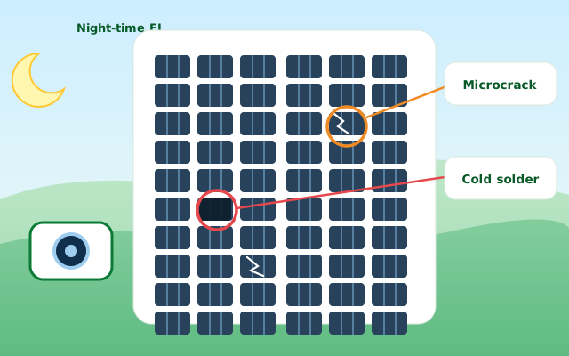
Look inside cells for cracks and bad solder joints. EL imaging makes a powered module glow so that cracks, broken fingers and poor solder joints show up as dark areas. It is usually done at night, on site, with a sensitive camera.
- Output losses with no visible damage
- Modules were transported or installed roughly
- You want evidence for a manufacturer claim
- A sample is needed to judge a batch of modules
- Reveals damage that no visual check or thermal image can see
- Supports warranty claims with clear images
- Shows whether damage is a one-off or a batch problem
How we do it, step by step.
Choose a sample that covers different strings, batches and locations.
Apply current to the module in the dark and capture the EL image.
Label microcracks, cold solder, inactive areas and finger interruptions.
Pair images with IV curve readings to see which defects cost energy.
- Defect classification with image evidence
- An estimate of how widespread each defect type is in the sample
- A basis for deciding whether to claim, replace or monitor
Outcomes depend on what the inspection finds. Possibilities are labelled as such in every report.
- EL image for each tested module
- Defect summary table
- Claim-ready evidence pack
Instruments: Field EL camera with controlled power supply
Night-time EL testing leads to a warranty claim on 5,000+ modules
The defects were traced back to production, so the manufacturer agreed to a warranty claim and replaced more than 5,000 modules, worth almost EUR 500,000 at market value according to CEA.
Read the case →Other services
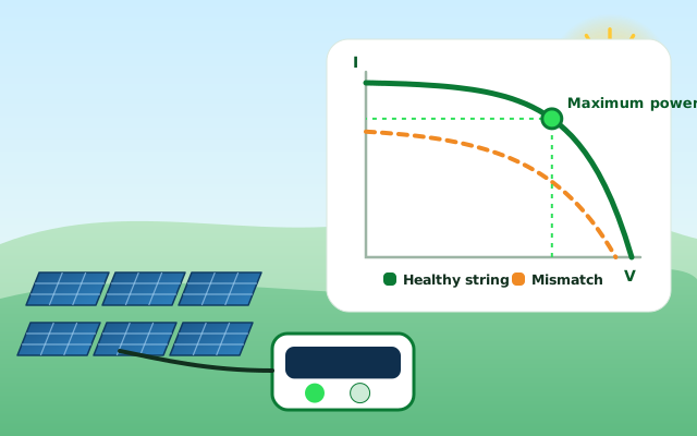
IV curve tracing
Measure what each string and module can really deliver.
See the process and outcomes →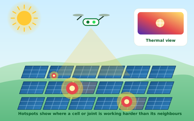
Thermography
See heat problems from the ground or from the air.
See the process and outcomes →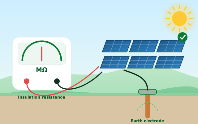
Insulation and earthing tests
Check the plant is safe, and leaking no energy to ground.
See the process and outcomes →Want this test on your plant?
Send an enquiry and we will prepare a checklist for your site.